Thread Charts
Fluid Port and Connector
Identification Guide
Quick Links
- Abbreviations
- Introduction
- American Connections
- National Pipe Tapered Fuel (NPTF)
- National Pipe straight mechanical (NSPM)
- JIC 37° Flare (SAE J514)
- SAE 45° Flare (SAE J512)
- SAE Straight Thread O-ring (O-Ring Boss)
- Flareless compression (SAE J514)
- O-Ring Face Seal (SAE J1453)
- SAE Inverted Flare (SAE J512)
- Four-Bolt Flange (SAE J518 and ISO 6162)
- O-Ring Pilot Threads
- International Connections
- British Standard Pipe
- British Standard Pipe Parallel (BSPP)
- British Standard Pipe Tapered (BSPT))
- Flat Face Port with British Standard Pipe Parallel Threads (ISO 1179-1)
- Flat Face Port with Metric Threads (ISO 9974-1)
- ISO 6149 Metric Port and Stud Ends
- Metric 600o Cone
- Metric tube compression (DIN 2353 240 Cone)
- Japanese Industrial Standard JIS 300 Flare
- Komatsu 30° Flare (JIS Metric)
Abbreviations
| NPTF | National Pipe Tapered Fuel |
| NPSM | National Pipe Straight Mechanical |
| ISO | International Standards Organization |
| SAE | Society of Automotive Engineers |
| JIC | Joint Industrial Council |
| NFPA | National Fluid Power Association |
| BSP | British Standard Pipe |
| DIN | Deutsche Industrial Norme |
| JIS | Japanese Industrial Standard |
| BSPT | British Standard Pipe Tapered |
| BSPP | British Standard Pipe Parallel |
Introduction
Ports and connectors have wide applications in fluid piping systems. Before you replace or add a hose or a tube to your assembly, you should identify the port or connector required by your fluid piping system. This guide will help you to identify them with ease.
A thread standard defines the form, angle, diameter, and pitch of a thread. ASME B1 .1 and ISO 261 are examples of standards that are commonly used by thread manufacturers.
Some of the organizations that have developed commonly used thread standards include American Society of Manufacturing Engineers, American National Standards Institute, International Organization for Standardization, SAE International, British Association, and Deutsches Institut für Normung.
Fluid port and connector identification tools
Calipers
This tool is used for measuring inner and outer thread diameters
Thread Pitch Gauge
A thread pitch gauge is used for determining the number of threads per inch. It is also used for measuring the thread-to-thread spacing in metric connections.
Accurate measurement of threads
Before you start measuring the threads of your fluid pipe or tube, ensure that they are in good conditions. Distorted or worn out threads can give you inaccurate measurements. After confirming that your threads are in good conditions, measure their diameter and record. An I.D./O.D. caliper is a suitable tool for this. Match the dimensions provided in this guide with your recorded measurements.
It is important to note that your measurements may not accurately match with the values provided in this guide. The slight differences are mainly caused by manufacturing tolerances.
After measuring the diameter of your threads, determine their spacing in threads per inch. In the case of metric connections, measure the thread-to-thread distances. To get an accurate value, ensure that the thread pitch gauge is fitting well on the threads. Record the values and compare your measurements with the figures provided in this guide.
Accurate measurement of four-bolt flanges
To start with, use a caliper to determine the port hole diameter of your bolt. After recording the value, measure the center to center bolt hole distance and record the longest spacing.
Dash numbers
Dash numbers are commonly used to describe the sizes of tubes and fluid pipes. These abbreviations are widely used in component ordering. To describe a fluid pipe or a tube in dash numbers, only the numerator part of the fraction is used. The denominator, always 16, is usually ignored. For instance, a -8 size means 8/16 or 1/2 an inch. It is important to note that dash numbers are nominal.
Dash numbers are not applicable to metric threads. Metric measurements give actual sizes of a tube or a fluid pipe. For instance, M12x1.0 means that the threads have an outer diameter of 12 mm and an inter-thread spacing of 1.0 mm.
American Connections
National Pipe Tapered Fuel (NPTF)
The NPTF is a dryseal thread. The male thread mates with the female thread and a seal is formed when the two are crushed together i.e. threads deformation. Teflon and pipe dope are commonly used when additional sealing is needed. Although this connection is widely used in fluid piping systems, the National Fluid Power Association (NFPA) does not recommend it for hydraulic applications.
NB: Although the NPTF connector and BSPT connector are similar in appearance, the two are not interchangeable.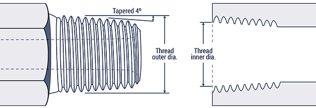
| Inch size | Dash size | Threads per Inch | Male Thread O.D. (in) | Female thread O.D (in) | ||
| 1⁄8 | -2 | 27 | 13⁄32 | 0.41 | 3⁄8 | 0.38 |
| 1⁄4 | -4 | 18 | 17⁄32 | 0.54 | 1⁄2 | 0.49 |
| 3⁄8 | -6 | 18 | 11⁄16 | 0.68 | 5⁄8 | 0.63 |
| 1⁄2 | -8 | 14 | 27⁄32 | 0.84 | 25⁄32 | 0.77 |
| 3⁄4 | -12 | 14 | 1 1⁄16 | 1.05 | 1 | 0.98 |
| 1 | -16 | 11 1⁄2 | 1 5⁄16 | 1.32 | 1 1⁄4 | 1.24 |
| 1 1⁄4 | -20 | 11 1⁄2 | 1 21⁄32 | 1.66 | 1 19⁄32 | 1.58 |
| 1 1⁄2 | -24 | 11 1⁄2 | 1 29⁄32 | 1.90 | 1 13⁄16 | 1.82 |
| 2 | -32 | 11 1⁄2 | 2 3⁄8 | 2.38 | 2 5⁄16 | 2.30 |
National Pipe straight mechanical (NPSM)
The male and female threads of the NSPM connection are straight. In addition, the male has a 300 internal chamfer while the female has an inverted 300 seat. A mechanical connection is formed when the two halves are threaded together. The tapered seat forms a leak-resistant joint. NSPM connections find many applications in fluid power systems.
NB: A NPSM female can form a seal with a chamfered NPTF male.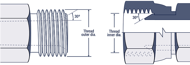
| Inch size | Dash size | Threads per Inch | Male Thread O.D. (in) | Female thread O.D (in) | ||
| 1⁄8 | -2 | 27 | 13⁄32 | 0.41 | 3⁄8 | 0.38 |
| 1⁄4 | -4 | 18 | 17⁄32 | 0.54 | 1⁄2 | 0.49 |
| 3⁄8 | -6 | 14 | 11⁄16 | 0.68 | 5⁄8 | 0.63 |
| 1⁄2 | -8 | 14 | 27⁄32 | 0.84 | 25⁄32 | 0.77 |
| 3⁄4 | -12 | 14 | 1 1⁄16 | 1.05 | 1 | 0.98 |
| 1 | -16 | 11 1⁄2 | 1 5⁄16 | 1.32 | 1 1⁄4 | 1.24 |
| 1 1⁄4 | -20 | 11 1⁄2 | 1 21⁄32 | 1.66 | 1 19⁄32 | 1.58 |
| 1 1⁄2 | -24 | 11 1⁄2 | 1 29⁄32 | 1.90 | 1 13⁄16 | 1.82 |
| 2 | -32 | 11 1⁄2 | 2 3⁄8 | 2.38 | 2 5⁄16 | 2.30 |
JIC 37° Flare (SAE J514)
This connection finds many applications in hydraulic systems. Both the JIC male and JIC female have a 37º flare seat and straight threads. The male and female flare seats seal when the straight threads are engaged. The connection is held mechanically by the straight threads of the male and female halves. It is important to note that most SAE J514 threads are identical to SAE 45º flare threads but their seating angles are different.
| Inch size | Dash size | Thread Size | Male Thread O.D. (in) | Female thread O.D (in) | ||
| 1⁄8 | -2 | 5⁄16 - 24 | 5⁄16 | 0.31 | 9⁄32 | 0.27 |
| 3⁄16 | -3 | 3⁄8 - 24 | 3⁄8 | 0.38 | 11⁄32 | 0.34 |
| 1⁄4 | -4 | 7⁄16 - 20 | 7⁄16 | 0.44 | 13⁄32 | 0.39 |
| 5⁄16 | -5 | 1⁄2 - 20 | 1⁄2 | 0.50 | 15⁄32 | 0.45 |
| 3⁄8 | -6 | 9⁄16 - 18 | 9⁄16 | 0.56 | 17⁄32 | 0.51 |
| 1⁄2 | -8 | 3⁄4 - 16 | 3⁄4 | 0.75 | 11⁄16 | 0.69 |
| 5⁄8 | -10 | 7⁄8 - 14 | 7⁄8 | 0.88 | 13⁄16 | 0.81 |
| 3⁄4 | -12 | 1 1⁄16 - 12 | 11⁄16 | 1.06 | 1 | 0.98 |
| 7⁄8 | -14 | 1 3⁄16 - 12 | 1 3⁄16 | 1.19 | 1 1⁄8 | 1.10 |
| 1 | -16 | 1 5⁄16-12 | 1 5⁄16 | 1.31 | 1 1⁄4 | 1.23 |
| 1 1⁄4 | -20 | 1 5⁄8 - 12 | 1 5⁄8 | 1.63 | 1 9⁄16 | 1.54 |
| 1 1⁄2 | -24 | 1 7⁄8 - 12 | 1 7⁄8 | 1.88 | 1 13⁄16 | 1.79 |
| 2 | -32 | 2 1⁄2 - 12 | 2 1⁄2 | 2.50 | 2 7⁄16 | 2.42 |
SAE 45° Flare (SAE J512)
The SAE 45° Flare connections are commonly used for low pressure applications such as refrigerant lines, fuel lines, and automotive piping systems. Both the SAE male and female halves have a 45° flare seat. The threads of the two halves engage to form a strong mechanical connection. The seal is formed on the 45° flare seat. Except for the seat angles, the SAE 45° Flare connectors are identical to JIC 37° Flare connectors.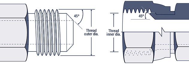
| Inch size | Dash size | Thread Size | Male Thread O.D. (in) | Female thread O.D (in) | ||
| 1⁄8 | -2 | 5⁄16 - 24 | 5⁄16 | 0.31 | 9⁄32 | 0.27 |
| 3⁄16 | -3 | 3⁄8 - 24 | 3⁄8 | 0.38 | 11⁄32 | 0.34 |
| 1⁄4 | -4 | 7⁄16 - 20 | 7⁄16 | 0.44 | 13⁄32 | 0.39 |
| 5⁄16 | -5 | 1⁄2 - 20 | 1⁄2 | 0.50 | 15⁄32 | 0.45 |
| 3⁄8 | -6 | 5⁄8 - 18 | 5⁄8 | 0.63 | 9⁄16 | 0.57 |
| 1⁄2 | -8 | 3⁄4 - 16 | 3⁄4 | 0.75 | 11⁄16 | 0.69 |
| 5⁄8 | -10 | 7⁄8 - 14 | 7⁄8 | 0.88 | 13⁄16 | 0.81 |
| 3⁄4 | -12 | 1 1⁄16 - 14 | 11⁄16 | 1.06 | 1 | 0.99 |
| 7⁄8 | -14 | 1 1⁄4 - 12 | 1 1⁄4 | 1.25 | 1 5⁄32 | 1.16 |
| 1 | -16 | 1 3⁄8 - 12 | 1 3⁄8 | 1.38 | 1 9⁄32 | 1.29 |
SAE Straight Thread O-ring (O-Ring Boss)
SAE J1926-1 and ISO 11296-1
The male connector of the O-Ring Boss has an O-ring and a straight thread. The female port has a sealing face, a chamfer, and a straight thread. The O-ring is compressed into the chamfer to form a seal. The threads of the two halves engage to form a mechanically strong connection. This connection finds many applications in high pressure hydraulic systems.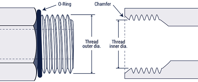
| Inch size | Dash size | Thread Size | Male Thread O.D. (in) | Female thread O.D (in) | ||
| 1⁄8 | -2 | 5⁄16 - 24 | 5⁄16 | 0.31 | 9⁄32 | 0.27 |
| 3⁄16 | -3 | 3⁄8 - 24 | 3⁄8 | 0.38 | 11⁄32 | 0.34 |
| 1⁄4 | -4 | 7⁄16 - 20 | 7⁄16 | 0.44 | 13⁄32 | 0.39 |
| 5⁄16 | -5 | 1⁄2 - 20 | 1⁄2 | 0.50 | 15⁄32 | 0.45 |
| 3⁄8 | -6 | 9⁄16 - 18 | 9⁄16 | 0.56 | 17⁄32 | 0.51 |
| 1⁄2 | -8 | 3⁄4 - 16 | 3⁄4 | 0.75 | 11⁄16 | 0.69 |
| 5⁄8 | -10 | 7⁄8 - 14 | 7⁄8 | 0.88 | 13⁄16 | 0.81 |
| 3⁄4 | -12 | 1 1⁄16 - 12 | 1 1⁄16 | 1.06 | 1 | 0.98 |
| 7⁄8 | -14 | 1 3⁄16 - 12 | 1 3⁄16 | 1.19 | 1 1⁄8 | 1.10 |
| 1 | -16 | 1 5⁄16 - 12 | 1 5⁄16 | 1.31 | 1 1⁄4 | 1.23 |
| 1 1⁄4 | -20 | 1 5⁄8 - 12 | 1 5⁄8 | 1.63 | 1 9⁄16 | 1.54 |
| 1 1⁄2 | -24 | 1 7⁄8 - 12 | 1 7⁄8 | 1.88 | 1 13⁄16 | 1.79 |
| 2 | -32 | 2 1⁄2 - 12 | 2 1⁄2 | 2.50 | 2 7⁄16 | 2.42 |
Flareless Compression (SAE J514)
The male of the flareless tube has a 240 seat and a straight thread. The female half has a compression sleeve and a straight thread. In addition to the sleeve, a female nut and a tube form part of the female connection. On the male, the seal takes place between the 24O seat and the compression sleeve. On the female, the seal takes place between the tubing and the compression sleeve. The threads engage to form a mechanically strong connection.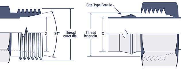
| Inch size | Dash size | Thread Size | Male Thread O.D. (in) | Female thread O.D (in) | ||
| 1⁄8 | -2 | 5⁄16 - 24 | 5⁄16 | 0.31 | 9⁄32 | 0.27 |
| 3⁄16 | -3 | 3⁄8 - 24 | 3⁄8 | 0.38 | 11⁄32 | 0.34 |
| 1⁄4 | -4 | 7⁄16 - 20 | 7⁄16 | 0.44 | 13⁄32 | 0.39 |
| 5⁄16 | -5 | 1⁄2 - 20 | 1⁄2 | 0.50 | 15⁄32 | 0.45 |
| 3⁄8 | -6 | 9⁄16 - 18 | 9⁄16 | 0.56 | 17⁄32 | 0.51 |
| 1⁄2 | -8 | 3⁄4 - 16 | 3⁄4 | 0.75 | 11⁄16 | 0.69 |
| 5⁄8 | -10 | 7⁄8 - 14 | 7⁄8 | 0.88 | 13⁄16 | 0.81 |
| 3⁄4 | -12 | 1 1⁄16 - 12 | 11⁄16 | 1.06 | 1 | 0.98 |
| 7⁄8 | -14 | 1 3⁄16 - 12 | 1 3⁄16 | 1.19 | 1 1⁄8 | 1.10 |
| 1 | -16 | 1 5⁄16 - 12 | 1 5⁄16 | 1.31 | 1 1⁄4 | 1.23 |
| 1 1⁄4 | -20 | 1 5⁄8 - 12 | 1 5⁄8 | 1.63 | 1 9⁄16 | 1.54 |
| 1 1⁄2 | -24 | 1 7⁄8 - 12 | 1 7⁄8 | 1.88 | 1 13⁄16 | 1.79 |
| 2 | -32 | 2 1⁄2 - 12 | 2 1⁄2 | 2.50 | 2 7⁄16 | 2.42 |
O-Ring Face Seal (SAE J1453)
This O-Ring Face Seal connection offers an impressive leak resistance and it is suitable for applications that are up to 6000 psi. The male contact has an O-ring and a straight thread. The female contact has a flat surface and a straight thread. A seal is formed when the O-ring in the face of the male end is compressed onto the machined flat surface female seat. The swivel female nut mechanically holds the connection.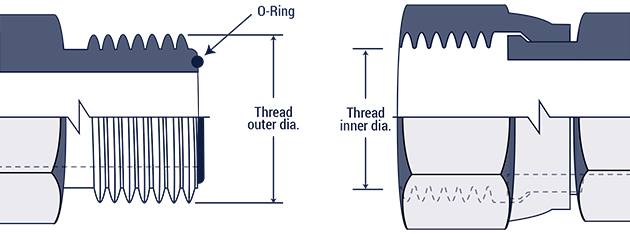
| Inch size | Dash size | Thread Size | Male Thread O.D. (in) | Female thread O.D (in) | ||
| 1⁄4 | -4 | 9⁄16 - 18 | 9⁄16 | 0.56 | 17⁄32 | 0.51 |
| 3⁄8 | -6 | 11⁄16 - 16 | 11⁄16 | 0.69 | 5⁄8 | 0.63 |
| 1⁄2 | -8 | 13⁄16 - 16 | 13⁄16 | 0.82 | 3⁄4 | 0.75 |
| 5⁄8 | -10 | 1 - 14 | 1 | 1.00 | 15⁄16 | 0.93 |
| 3⁄4 | -12 | 1 3⁄16 - 12 | 13⁄16 | 1.19 | 1 1⁄8 | 1.11 |
| 1 | -16 | 1 7⁄16 - 12 | 1 7⁄16 | 1.44 | 1 3⁄4 | 1.36 |
| 1 1⁄4 | -20 | 1 11⁄16 - 12 | 1 11⁄16 | 1.69 | 15⁄8 | 1.61 |
| 1 1⁄2 | -24 | 2-12 | 2 | 2.00 | 1 15⁄16 | 1.92 |
SAE Inverted Flare (SAE J512)
The inverted flare finds many applications in automotive systems. A machined male connector has a 420 seat.A flared male tubing has a 450 seat. The female end of the inverted flare has a 420 seat that provides a sealing surface. Threads engage to form a mechanically strong connection.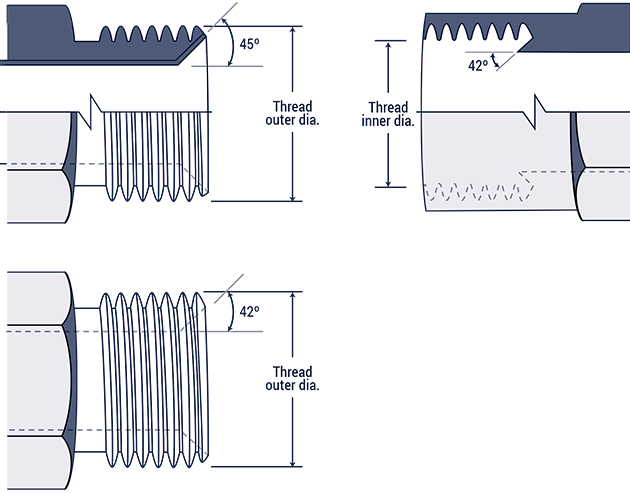
| Inch size | Dash size | Thread Size | Male Thread O.D. (in) | Female thread O.D (in) | ||
| 1⁄8 | -2 | 5⁄16 - 28 | 5⁄16 | 0.31 | 9⁄32 | 0.27 |
| 3⁄16 | -3 | 3⁄8 - 24 | 3⁄8 | 0.38 | 11⁄32 | 0.34 |
| 1⁄4 | -4 | 7⁄16 - 24 | 7⁄16 | 0.44 | 13⁄32 | 0.39 |
| 5⁄16 | -5 | 1⁄2 - 20 | 1⁄2 | 0.50 | 15⁄32 | 0.45 |
| 3⁄8 | -6 | 5⁄8 - 18 | 5⁄8 | 0.63 | 9⁄16 | 0.57 |
| 7⁄16 | -7 | 11⁄16 - 18 | 11⁄16 | 0.69 | 5⁄8 | 0.63 |
| 1⁄2 | -8 | 3⁄4 - 18 | 3⁄4 | 0.75 | 23⁄32 | 0.70 |
| 5⁄8 | -10 | 7⁄8 - 18 | 7⁄8 | 0.88 | 13⁄16 | 0.81 |
| 3⁄4 | -12 | 1 1⁄16 - 16 | 11⁄16 | 1.06 | 1 | 1.00 |
Four-Bolt Flange (SAE J518 and ISO 6162)
The Four-Bolt Flange is suitable for connecting 1/2" to 3" hoses and tubings and it is widely used in fluid power systems.The O-ring seats on the ring groove of the male. The seal takes place between the O-ring on the male and the smooth face of the female port. Four bolts and two clamp halves hold the connection in place.
SAE J518 flanges are available in two pressure categories: standard (code 61) and high pressure (code 62).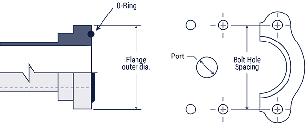
| Inch size | Dash size | Code 61 Bolt Spacing | Code 61 Flange O.D. | Code 62 Bolt Spacing | Code 62 Flange O.D. |
| 1⁄2 | -8 | 1 1⁄2 | 1 3⁄16 | 1 19⁄32 | 1 1⁄4 |
| 3⁄4 | -12 | 1 7⁄8 | 1 1⁄2 | 2 | 1 5⁄8 |
| 1 | -16 | 2 1⁄16 | 1 3⁄4 | 2 1⁄4 | 1 7⁄8 |
| 1 1⁄4 | -20 | 2 5⁄16 | 2 | 2 5⁄8 | 2 1⁄8 |
| 1 1⁄2 | -24 | 2 3⁄4 | 2 3⁄8 | 3 1⁄8 | 2 1⁄2 |
| 2 | -32 | 3 1⁄16 | 2 13⁄32 | 3 13⁄16 | 3 1⁄8 |
| 2 1⁄2 | -40 | 3 1⁄2 | 3 5⁄16 | n/a | n/a |
| 3 | -48 | 4 3⁄16 | 4 | n/a | n/a |
O-Ring Pilot Threads
The O-Ring Pilot Threads connection is commonly used in vehicle and commercial air conditioning systems. The male and female ends have a pilot and a seal is formed when the O-ring is compressed. The pilot can either be long or short. Threads engage to form a mechanically strong connection.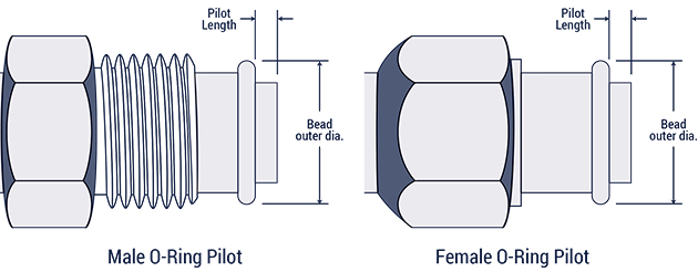
| Inch size | Dash size | Male Thread | Female thread | ||
| Thread size | Thread O.D. | Thread size | Thread I.D. | ||
| 3⁄8 | -6 | 5⁄8 - 18 | 5⁄8 | 5⁄8 - 18 | 9⁄16 |
| 1⁄2 | -8 | 3⁄4 - 18 | 3⁄4 | 3⁄4 - 16 | 11⁄16 |
| 5⁄8 | -10 | 7⁄8 - 18 | 7⁄8 | 7⁄8 - 14 | 13⁄16 |
| 3⁄4 | -12 | 1 1⁄16 - 16 | 1 1⁄16 | 1 1⁄16 - 14 | 1 |
| Inch size | Dash size | Long pilot | Short pilot | ||
| Bead O.D. (in) | Pilot Length (in) | Bead O.D. (in) | Pilot Length (in) | ||
| 3⁄8 | -6 | 0.52 | 0.28 | 0.52 | 0.19 |
| 1⁄2 | -8 | 0.64 | 0.39 | 0.64 | 0.19 |
| 5⁄8 | -10 | 0.77 | 0.39 | 0.77 | 0.19 |
| 3⁄4 | -12 | 0.91 | 0.39 | 0.91 | 0.19 |
International Connections
British Standard Pipe
The British connections are available in two classes: British Standard Pipe Parallel (BSPP)and British Standard Pipe Tapered (BSPT).
British Standard Pipe Parallel (BSPP)
The BSPP male end has a 300 seat. The tapered nose of the female swivel seals on the 300 seat of the male. Although the male end is similar to the American National Pipe Straight Mechanical (NPSM) male, the two are not interchangeable because their thread pitches are different.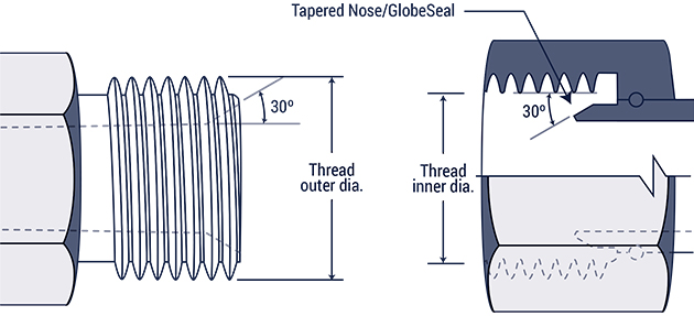
| Inch size | Dash size | Thread Size | Male Thread O.D. (in) | Female thread O.D (in) | ||
| 1⁄8 | -2 | 1⁄8 - 28 | 3⁄8 | 0.38 | 11⁄32 | 0.35 |
| 1⁄4 | -4 | 1⁄4 - 19 | 33⁄64 | 0.52 | 15⁄32 | 0.47 |
| 3⁄8 | -6 | 3⁄8 - 19 | 21⁄32 | 0.65 | 19⁄32 | 0.60 |
| 1⁄2 | -8 | 1⁄2 - 14 | 13⁄16 | 0.82 | 3⁄4 | 0.75 |
| 5⁄8 | -10 | 5⁄8 - 14 | 7⁄8 | 0.88 | 13⁄16 | 0.80 |
| 3⁄4 | -12 | 3⁄4 - 14 | 11⁄32 | 1.04 | 31⁄32 | 0.97 |
| 1 | -16 | 1 - 11 | 1 5⁄16 | 1.30 | 1 7⁄32 | 1.22 |
| 1 1⁄4 | -20 | 1 1⁄4 - 11 | 1 21⁄32 | 1.65 | 1 9⁄16 | 1.56 |
| 1 1⁄2 | -24 | 1 1⁄2 - 11 | 1 7⁄8 | 1.88 | 1 25⁄32 | 1.79 |
| 2 | -32 | 2 - 11 | 2 11⁄32 | 2.35 | 2 1⁄4 | 2.26 |
British Standard Pipe Tapered (BSPT)
The tapered male of the BSPT mates with a tapered female. The seal takes place on the threads. Although the BSPT male end is similar to the National Pipe Tapered Fuel (NPTF), the two are not interchangeable because their thread form and sizes are different.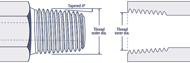
| Inch size | Dash size | Thread Size | Male Thread O.D. (in) | Female thread O.D (in) | ||
| 1⁄8 | -2 | 1⁄8 - 28 | 3⁄8 | 0.38 | 11⁄32 | 0.35 |
| 1⁄4 | -4 | 1⁄4 - 19 | 33⁄64 | 0.52 | 15⁄32 | 0.47 |
| 3⁄8 | -6 | 3⁄8 - 19 | 21⁄32 | 0.65 | 19⁄32 | 0.60 |
| 1⁄2 | -8 | 1⁄2 - 14 | 13⁄16 | 0.82 | 3⁄4 | 0.75 |
| 5⁄8 | -10 | 5⁄8 - 14 | 7⁄8 | 0.88 | 13⁄16 | 0.80 |
| 3⁄4 | -12 | 3⁄4 - 14 | 11⁄32 | 1.04 | 31⁄32 | 0.97 |
| 1 | -16 | 1 - 11 | 1 5⁄16 | 1.30 | 1 7⁄32 | 1.22 |
| 1 1⁄4 | -20 | 1 1⁄4 - 11 | 1 21⁄32 | 1.65 | 1 9⁄16 | 1.56 |
| 1 1⁄2 | -24 | 1 1⁄2 - 11 | 1 7⁄8 | 1.88 | 1 25⁄32 | 1.79 |
| 2 | -32 | 2 - 11 | 2 11⁄32 | 2.35 | 2 1⁄4 | 2.26 |
Flat Face Port with British Standard Pipe Parallel Threads (ISO 1179-1)
DIN 3852, Part 2
The parallel threads form a seal using a variety of sealing rings or washers. The seal takes place between the male end and the machined flat surface of the female.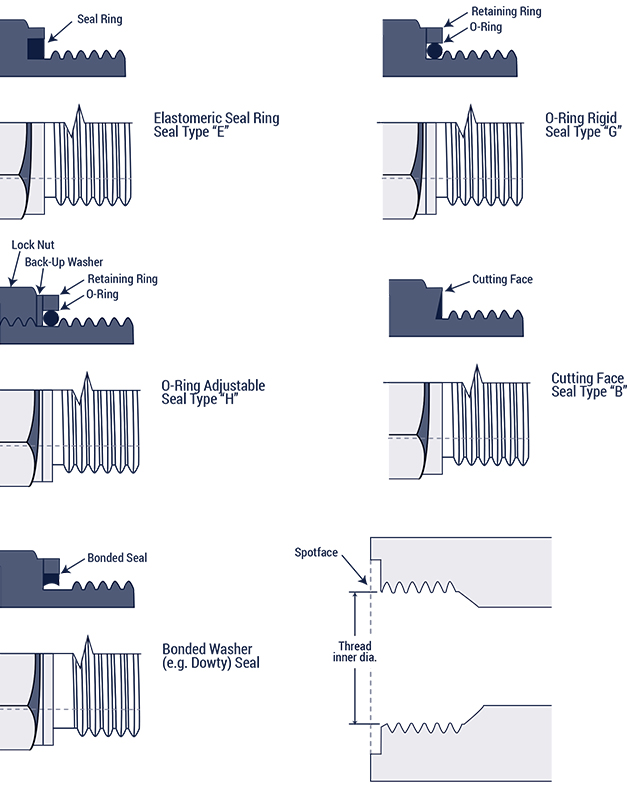
Flat Face Port with Metric Threads (ISO 9974-1)
DIN 3852, Part 1
The parallel threads form a seal using a variety of sealing rings or washers. The seal takes place between the male end and the machined flat surface of the female.
ISO 261 Metric threads
| Metric Thread Size | Male Thread O.D. (mm) | Female Thread I.D (mm) |
| M8 x 1.0 | 8 | 7 |
| M10 x 1.0 | 10 | 9 |
| M12 x 1.5 | 12 | 10.5 |
| M14 x 1.5 | 14 | 12.5 |
| M16 x 1.5 | 16 | 14.5 |
| M18 x 1.5 | 18 | 16.5 |
| M20 x 1.5 | 20 | 18.5 |
| M22 x 1.5 | 22 | 20.5 |
| M24 x 1.5 | 24 | 22.5 |
| M26 x 1.5 | 26 | 24.5 |
| M27 x 2.0 | 27 | 25 |
| M33 x 2.0 | 33 | 31 |
| M36 x 2.0 | 36 | 34 |
| M42 x 2.0 | 42 | 40 |
| M45 x 2.0 | 45 | 43 |
| M48 x 2.0 | 48 | 46 |
ISO 6149 Metric Port and Stud Ends
ISO 261 threads & O-ring seal
The male connector of the ISO 6149 connection has an O-ring and a straight thread. The female half has a machined surface, a chamfer, and a straight thread. The O-ring on the male sits on the chamfer of the female port. The ISO 6149 connection is similar to the SAE J1926-1O-ring Boss except that the former has metric threads. The O-ring on the male connector is compressed into the chamfer to create a seal. The straight threads engage to form a mechanically strong connection.
| Metric Thread Size | Male Thread O.D. (mm) | Female Thread I.D (mm) |
| M8 x 1.0 | 8 | 7 |
| M10 x 1.0 | 10 | 9 |
| M12 x 1.5 | 12 | 10.5 |
| M14 x 1.5 | 14 | 12.5 |
| M16 x 1.5 | 16 | 14.5 |
| M18 x 1.5 | 18 | 16.5 |
| M22 x 1.5 | 22 | 20.5 |
| M27 x 2.0 | 27 | 25 |
| M33 x 2.0 | 33 | 31 |
| M42 x 2.0 | 42 | 40 |
| M48 x 2.0 | 48 | 46 |
| M60 x 2.0 | 60 | 58 |
Metric 60° Cone
DIN 7631
The male of the Metric 60° Cone connection has a 60° recessed cone and a straight thread. The female half has a globeseal seat and a straight thread. The seal takes place between the 60° recessed cone and the tapered nose of the female. The threads of the two halves engage to form a mechanically strong connection. This connection finds many applications in hydraulic systems.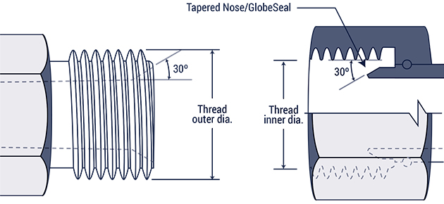
| Pipe/Tube O.D. (mm) | Metric Thread Size | Male Thread O.D. (mm) | Female Thread I.D (mm) |
| 6 | M12 x 1.5 | 12 | 10.5 |
| 8 | M14 x 1.5 | 14 | 12.5 |
| 10 | M16 x 1.5 | 16 | 14.5 |
| 12 | M18 x 1.5 | 18 | 16.5 |
| 15 | M22 x 1.5 | 22 | 20.5 |
| 18 | M26 x 1.5 | 26 | 24.5 |
| 22 | M30 x 1.5 | 30 | 28.5 |
| 28 | M38 x 1.5 | 38 | 36.5 |
| 35 | M45 x 1.5 | 45 | 43.5 |
| 52 | M52 x 1.5 | 52 | 50.5 |
Metric Tube Compression (DIN 2353 24° Cone)
The male has a 240 Cone and a straight thread. The three female connectors have straight threads and a sealing surface. The seal takes place between the 240 Cone on the male connector and the sealing areas on the females.
Fittings are available in two series: the DIN 2353 L (light) and the DIN 2353 S (heavy) classes. Each series has its own tube sizes and thread dimensions as shown in the table below: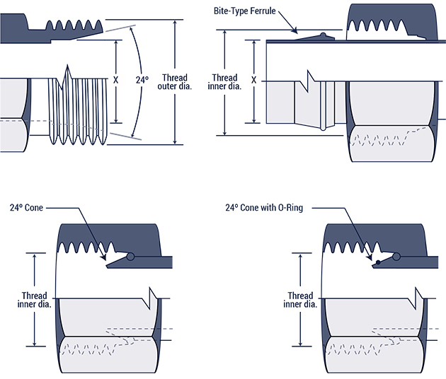
| DIN 2353 L Tube O.D.(mm) | DIN 2353 S Tube O.D. (mm) | Metric Thread Size | Male Thread O.D. (mm) | Female Thread I.D (mm) |
| 6 | M12 x 1.5 | 12 | 10.5 | |
| 8 | 6 | M14 x 1.5 | 14 | 12.5 |
| 10 | 8 | M16 x 1.5 | 16 | 14.5 |
| 12 | 10 | M18 x 1.5 | 18 | 16.5 |
| 12 | M20 x 1.5 | 20 | 18.5 | |
| 15 | 14 | M22 x 1.5 | 22 | 20.5 |
| 16 | M24 x 1.5 | 24 | 22.5 | |
| 18 | M26 x 1.5 | 26 | 24.5 | |
| 22 | 20 | M30 x 2.0 | 30 | 28 |
| 28 | 25 | M36 x 2.0 | 36 | 34 |
| 30 | M42 x 2.0 | 42 | 40 | |
| 35 | M45 x 2.0 | 45 | 43 | |
| 42 | 38 | M52 x 2.0 | 52 | 50 |
Japanese Industrial Standard JIS 300 Flare
The male has a 30° seat and a straight thread.The female half has a 300 seat and a straight thread.This connection is similar to 37° Flare. Its 30° seat and BSPP-like thread dimensions differentiate it from the American 37° Flare.
| Inch size | Dash size | Thread Size | Male Thread O.D. (in) | Female thread O.D (in) | ||
| 1⁄8 | -2 | 1⁄8 - 28 | 3⁄8 | 0.38 | 11⁄32 | 0.35 |
| 1⁄4 | -4 | 1⁄4 - 19 | 33⁄64 | 0.52 | 15⁄32 | 0.47 |
| 3⁄8 | -6 | 3⁄8 - 19 | 21⁄32 | 0.65 | 19⁄32 | 0.60 |
| 1⁄2 | -8 | 1⁄2 - 14 | 13⁄16 | 0.82 | 3⁄4 | 0.75 |
| 5⁄8 | -10 | 5⁄8 - 14 | 7⁄8 | 0.88 | 13⁄16 | 0.80 |
| 3⁄4 | -12 | 3⁄4 - 14 | 11⁄32 | 1.04 | 31⁄32 | 0.97 |
| 1 | -16 | 1 - 11 | 1 5⁄16 | 1.30 | 1 7⁄32 | 1.22 |
| 1 1⁄4 | -20 | 1 1⁄4 - 11 | 1 21⁄32 | 1.65 | 1 9⁄16 | 1.56 |
| 1 1⁄2 | -24 | 1 1⁄2 - 11 | 1 7⁄8 | 1.88 | 1 25⁄32 | 1.79 |
| 2 | -32 | 2 - 11 | 2 11⁄32 | 2.35 | 2 1⁄4 | 2.26 |
Komatsu 30° Flare (JIS Metric)
The Komatsu 30° Flare has parallel metric threads and a 30° seat. This connection is widely used on Komatsu equipment. The JIS metric connection is similar to the JIS 300 flare, except that the latter has BSPP-like thread dimensions.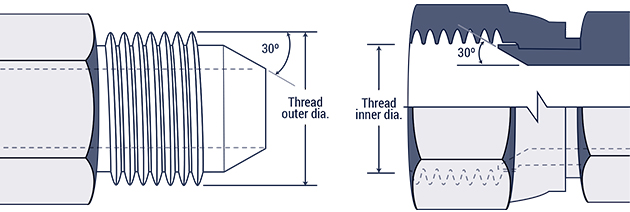
| Dash Size | Metric Thread Size | Male Thread O.D. (mm) | Female Thread I.D (mm) |
| -6 | M18 x 1.5 | 18 | 16.5 |
| -8 | M22 x 1.5 | 22 | 20.5 |
| -10 | M24 x 1.5 | 24 | 22.5 |
| -12 | M30 x 1.5 | 30 | 28.5 |
| -16 | M33 x 1.5 | 33 | 31.5 |
| -20 | M36 x 1.5 | 36 | 34.5 |
| -24 | M42 x 1.5 | 42 | 40.5 |